|
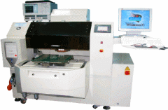
TDR 5100 | |
| Semi-Automatic RF Characteristic Impedance Tester |
|
|
TDR 5100 Automatic RF Characteristic Impedance Tester uses one PC as the controller and comprises Time-Domain Reflector (Agilent 86100 A / B or Tektronix TDS 8000B / 8200B), 18GHz microwave switching interface cards and test adapters. The tester can faithfully deliver RF signals from TDR to the traces on the PCB under test, and meet the requirement of short measurement distance and high accuracy. The tester adopts the design of using replaceable coaxial probes. The replaceable probes are convenient to maintain and equip ESD protection for preventing TDR modules from ESD damage. The system software has powerful and auto-learning functionality, and can output charts, data, failed board location and trace numbers according to test results. The operators can perform rapid repair for failed boards and store measured data by the format of Access database. The statistic charts are also provided to control production quality and yield improvement efficiently. The particular of TDR 5100 is capable of moving along 3 axes (X, Y, θ), especially for large-size, circular and more than 1000 points PCBs. | |
| Specification | ||
|
MODEL
|
TDR 5100 | |
|
․ |
MAINFRAME | DC TO 18GHz |
|
․ |
SWITCHING | DC TO 18GHz 30 CHANNEL |
|
․ |
GPIB CARD | GPIB CARD (including driver installation software) |
|
․ |
CABLE ASSEMBLY | DC TO 18GHz |
|
․ |
PROBE | DC TO 4GHz |
|
․ |
Airline | 28 ohm or 50 ohm |
|
․ |
Displacement with 3-axial motion X axis traveling 450~900mm, positioning accuracy ±0.05mm, servo drive (due to long traveling) Y axis traveling 450~900mm, positioning accuracy ±0.05mm, servo drive (due to long traveling) θ axis traveling 360°, positioning accuracy 0.01°, linear micro step and air-floating drive | |
|
․ |
GUI + Control Software + Signal Linking | |
|
․ |
TABEL Fast Switching (2) | |
|
․ |
Probes move along Z-axis only (micro step motor drive) | |
|
․ |
||
|
․ |
Suitable for RIMM、C-RIMM、main board and other Impedance PCB | |
|
․ |
Rise Time 35ps, Bandwidth 10GHz, Resolution 3mm | |
|
․ |
Minimum Injection Effect minimum ground 100p.l crosstalk | |
|
․ |
Accuracy 0.4% ≒ 0.1Ω (R&R Experiment) | |
|
․ |
Minimum Ground /signal Pitch 0.0235〞probe | |
|
․ |
60 Test Points (Max. Expandable 180 Test Points) | |
|
․ |
Test Time 3K Panel ×30 pts / 24 hrs | |
|
․ |
Capable of testing different impedance from 25Ω to 150Ω simultaneously | |
|
․ |
Real differential impedance measurement (Inject positive and negative pulses simultaneously) | |
|
․ |
Providing both of automatic and manual modes: 1. Automatic mode is normal on-line operation. 2. Manual Mode can capture waveforms, store waveforms, print waveforms and adjust measurement range manually. | |
|
․ |
Providing 2 standard air lines: 50Ω and 28Ω | |
|
․ |
The 18GHz switch system is Plug & Play and easy to use and maintain. | |
